Congratulations to @NickBrown for his solution! Based on that equation and some additional references I'll just add a little more.
Calculating visual magnitude takes three input parameters
- how good of a reflector the object is
- the angle between the illumination and the viewing
- the distances from illuminator and viewer are from the object
For astronomical objects we use absolute magnitude for item #1, for satellite viewing both absolute magnitude and intrinsic magnitude are used. Absolute magnitude is the visual magnitude of the object at 1 AU from the Sun and 1 AU from you, viewed full-on (phase angle = 0) which means you are sitting right next to the Sun.
Intrinsic magnitude is similar, but you are now only 1,000 km from the object with the Sun over your shoulder.
Either way, all of the albedo, size and shape information is lumped into the absolute or intrinsic magnitude, leaving only distances and angles.
The angle between the direction of illumination and the direction of viewing is called the phase angle. Think phases of the Moon for example. If the phase angle of the Moon were 90 degrees, it would be a half-moon. Zero would be full Moon and 180 degrees would be new Moon.
The modulation of the brightness as a function of phase angle was proposed by Vallerie, E.M. III, Investigation of Photometric Data Received from an Artificial Earth Satellite, AD #419069, Air Force Institute of Technology, Defense Documentation Center, Alexandria, Virginia, 1963, which I found in Observations and Modeling of GEO Satellites at Large Phase Angles by Rita L. Cognion, also in Researchgate
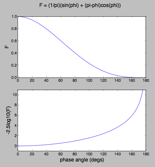
The dependence is given by the term
$$ \frac{1}{\pi}(\sin(\phi) + (\pi-\phi) \cos(\phi))$$
and looks like

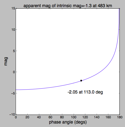
For the satellite in the question at a distance of 483 kilometers and an intrinsic magnitude of -1.3, the the apparent magnitude seems to be about -2.0 and its dependence on phase angle is as follows:

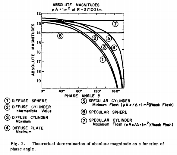
Not all spacecraft are spherical with diffuse white surfaces nor spherical-cow-shaped.

For phase angle dependence of some more familliar shapes, see Figure 2 in Visible Magnitude of Typical Satellites in Synchronous Orbits William E. Krag, MIT, 1974 AD-785 380, which describes the problem nicely.

def Mapparent_from_Mintrinsic(Mint, d_km, pa):
    term_1 = Mint
    term_2 = +5.0 * np.log10(d_km/1000.)
    arg    = np.sin(pa) + (pi - pa) * np.cos(pa)
    term_3 = -2.5 * np.log10(arg)
    return term_1 + term_2 + term_3

import numpy as np
import matplotlib.pyplot as plt

halfpi, pi, twopi = [f*np.pi for f in (0.5, 1, 2)]
degs, rads = 180/pi, pi/180

Mintrinsic   = -1.3
d_kilometers = 483.

phase_angles = np.linspace(0, pi, 181)

Mapp = Mapparent_from_Mintrinsic(Mintrinsic, d_kilometers, phase_angles)

# https://astronomy.stackexchange.com/q/28744/7982
# https://www.researchgate.net/publication/268194552_Large_phase_angle_observations_of_GEO_satellites
# https://amostech.com/TechnicalPapers/2013/POSTER/COGNION.pdf
# https://apps.dtic.mil/dtic/tr/fulltext/u2/785380.pdf

if True:
    plt.figure()

    F = (1./pi)*(np.sin(phase_angles) + (pi-phase_angles)*np.cos(phase_angles))

    plt.suptitle('F = (1/pi)(sin(phi) + (pi-phi)cos(phi))', fontsize=16)

    plt.subplot(2, 1, 1)
    plt.plot(degs*phase_angles, F)
    plt.ylabel('F', fontsize=16)

    plt.subplot(2, 1, 2)
    plt.plot(degs*phase_angles, -2.5*np.log10(F))
    plt.xlabel('phase angle (degs)', fontsize=16)
    plt.ylabel('-2.5log10(F)', fontsize=16)
    plt.ylim(-1, 11)

    plt.show()

if True:
    plt.figure()
    plt.plot(degs*phase_angles, Mapp)
    plt.plot(degs*phase_angles[113], Mapp[113], 'ok')
    plt.text(90, -5, '{:0.2f} at {:0.1f} deg'.format(Mapp[113], 113), fontsize=16)
    plt.xlabel('phase angle (degs)', fontsize=16)
    plt.ylabel('mag', fontsize=16)
    plt.title('apparent mag of intrinsic mag=-1.3 at 483 km', fontsize=16)
    plt.ylim(-10, 15)
    plt.show()


