I can think of at least four very different ways that "astronomers convert radio signals received by their antenna to images."
1. Scanning
This is the oldest and easiest to understand way to image. The answer to the question How did single dish (or single receiver) radio telescopes originally generate images? sums it up concisely:
They scan the object, if you point the dish a a point in the sky as the Earth rotates the dish scans across astronomical objects, then move the dish to point at a slightly different position and let it scan across the object again, and again. After a while you can re-construct an image from the scan lines in a similar way to analogue TV.
Here is an early 1D projection of scanning the plane of our Milky Way galaxy from The galactic system as a spiral nebula Oort, J. H.; Kerr, F. J.; Westerhout, G. MNRAS 118, (1958) p. 379. This image is reversed tone for better clarity.
For more information see answer(s) to Why the blank wedges in this very early 21 cm map of the Milky Way? (Oort et al. 1958)

2. Interferometry (most common technique today)
If you receive an incoming wavefront from two or more different locations, which in this case means two or more antennas, you can use math to reconstruct an image. This is called interferometric imaging and these days it's done by feeding the signals from each antenna to a large, fast computer known as a correlator. However in the early days of interferometric imaging the interference was actually done electronically, with amplified signals from each antenna combined in a mixer and other electronics.
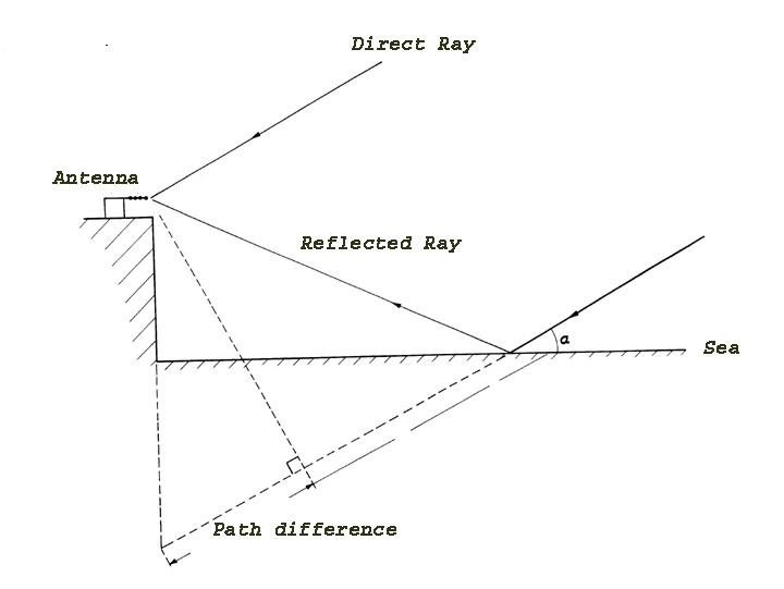
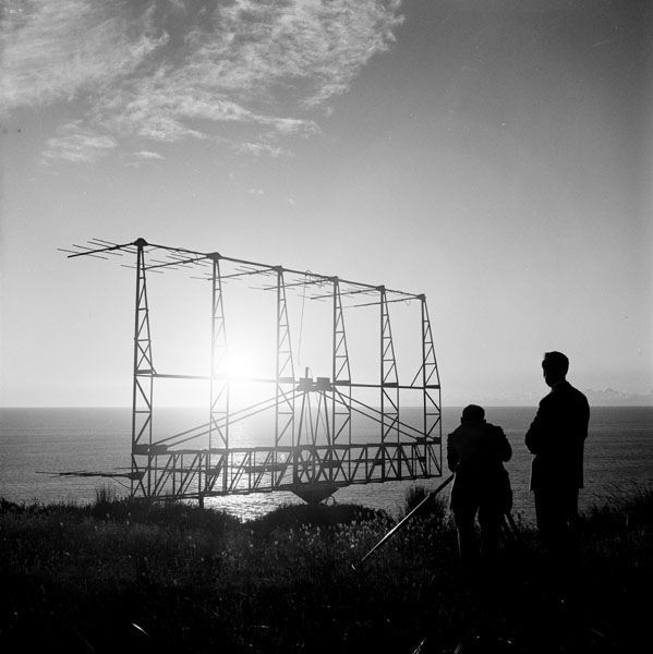
In fact, one of the earliest techniques of radio interferometry used a single antenna which collected both a direct signal from the source and a signal taking a longer path by reflecting off of water! This is called Sea interferometry and in this case the water acts as a Lloyd's Mirror. This is one dimensional imaging only.
Read more about this in Radio Astronomy at Dover Heights as well as in the paper Galactic Radiation at Radio Requencies V. The Sea Interferometer J. G. Bolton and O. B. Slee, Australian Journal of Physics, vol. 6, p.420, December 1953.
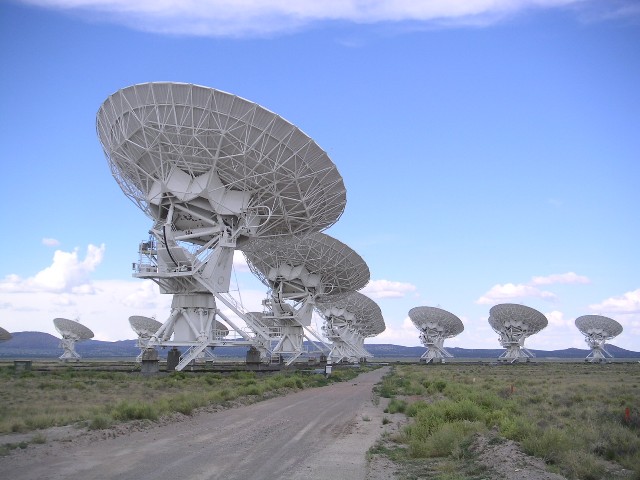
above: Very Large Array (Source)
You may have seen images of (material around) a black hole recently. In this case the signals from each antenna were recorded on to hard drives, which were then shipped to a central location before being put into a computer correlator, but mathematically it is the same process. See answer(s) to How does the Event Horizon Telescope implement the interferometry?
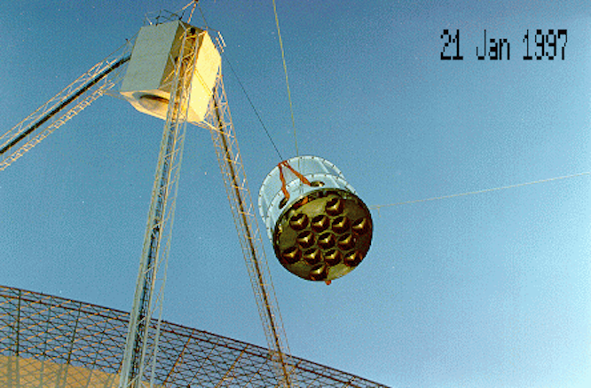
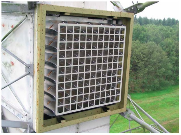
3. Direct imaging using focal plane arrays
The question What is the highest granularity focal-plane array on a dish radio telescope? Or is this the ONLY ONE? shows the first image below, of the Parkes 21cm Multibeam Receiver and seems to be dated 1997. In this answer links to First image with Apertif: a new life for the Westerbork radio telescope which is shown in the second image.
4. Delay-Doppler radar
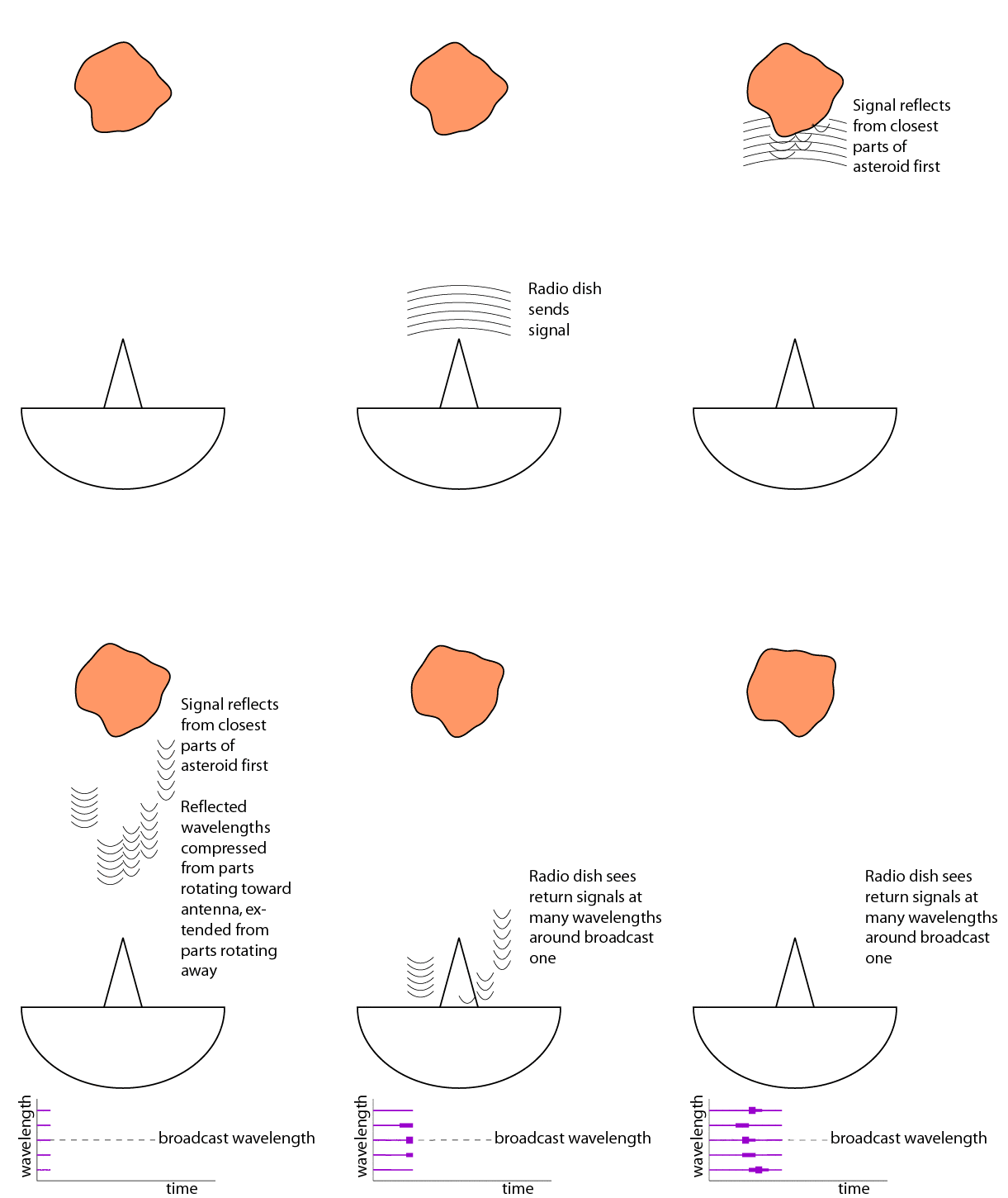
This is the coolest method! It is based on radar, which means that from one dish astronomers beam a carefully modulated radio signal towards a planet or asteroid, and receive the reflected beam in a separate dish. This kind of radar is called delay-doppler because it extracts two kinds of information from the returned signal, the total delay time giving distances, and the doppler shift caused by the velocity of the surface doing the reflecting.
If the body is rotating, different areas will be moving towards or away from us depending on their location, and different parts will be closer or farther away from us, also depending on location. If they receive enough signals over a long enough period of time, they can reconstruct a hypothetical image of the shape of the object.
See The Planetary Society's Senior Editor and Planetary Evangelist Emily Lakdawalla's How radio telescopes get "images" of asteroids and this answer for more on this technique.
Left: A very slow GIF Source.
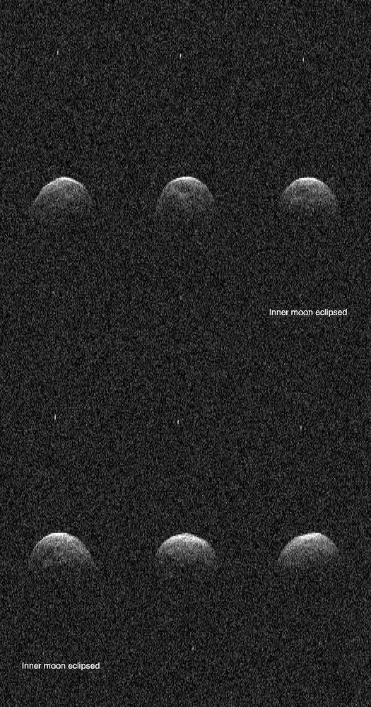
Right: A radar image shows asteroid 3122 Florence and tiny echoes from its two moons. Here is an animation that shows them more clearly. The direction of the radar illumination (and thus the direction toward Earth) is at the top." From here. NASA / Jet Propulsion Laboratory. This is a small subset of the frames contained in the original 36 MB GIF, and the size has been decreased by a factor of 2 in order to fit in SE's 2 MB limit. From the question What is the physical geometry of this apparent "eclipse" of a tiny moon of Asteroid Florence?
Note: These two images do not necessarily have the same orientation.
